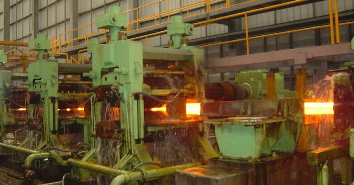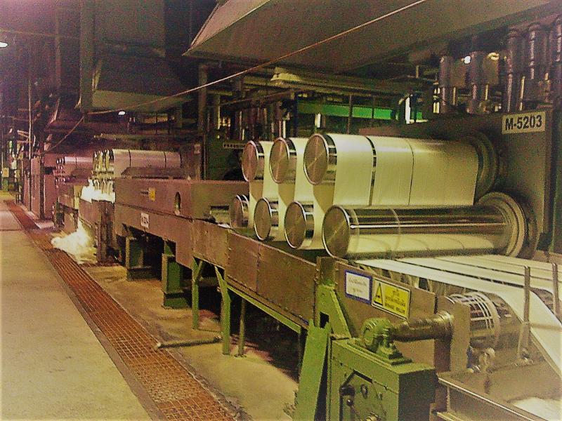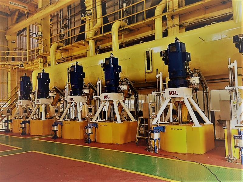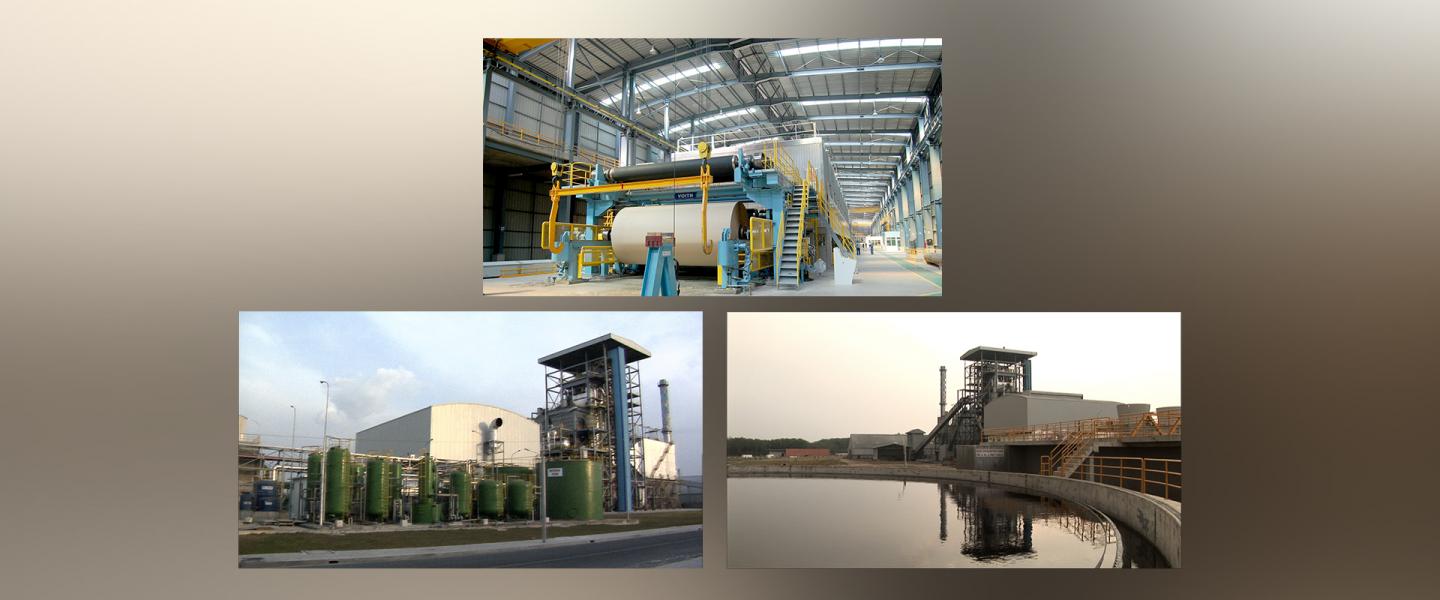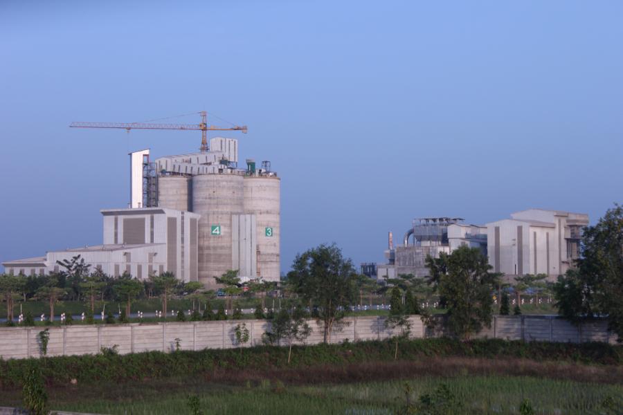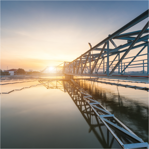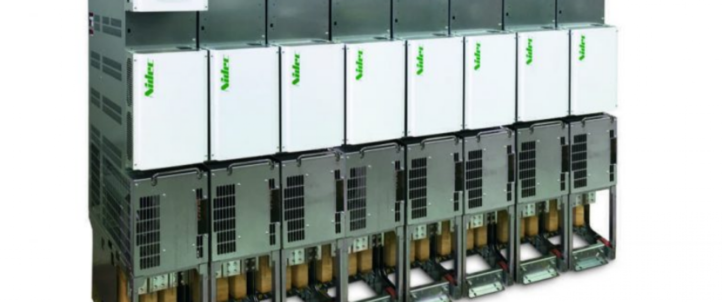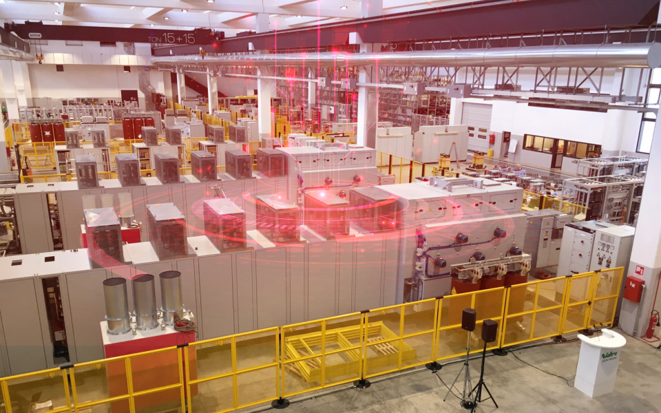


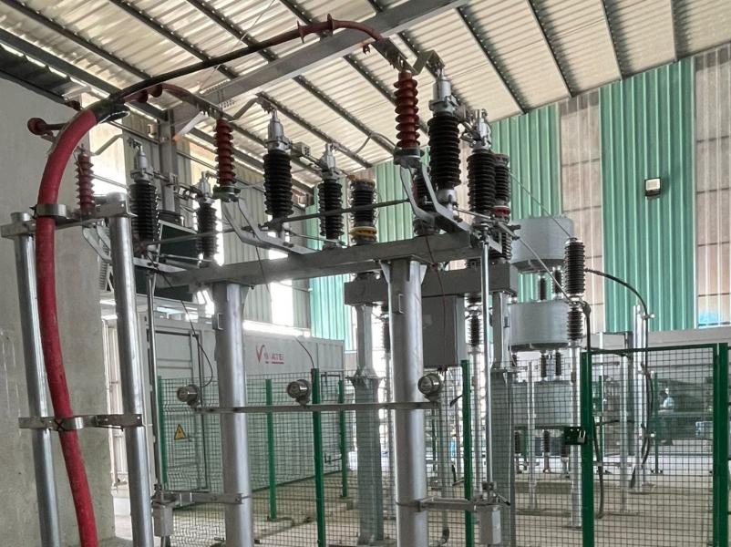
การติดตั้งระบบ Static VAR Generator (SVG/STATCOM) 20kV สำหรับโรงรีดเหล็กแผ่นชั้นนำในอินโดนีเซีย
กลุ่มเหล็ก
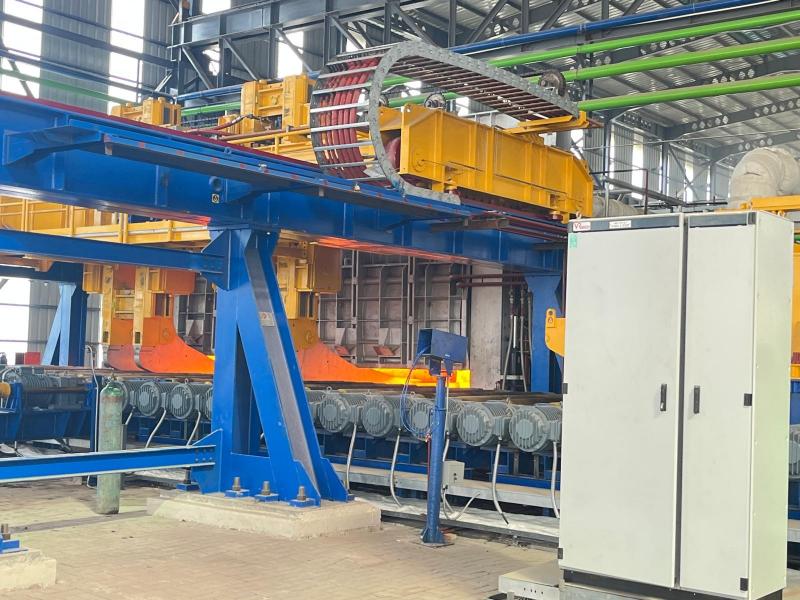
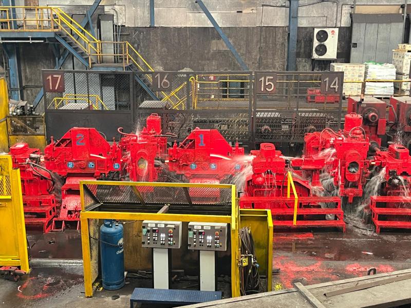
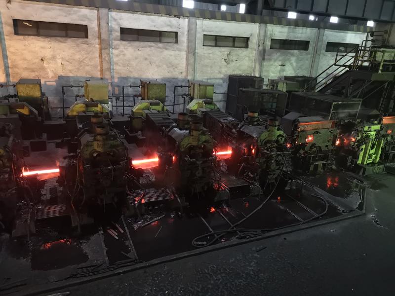
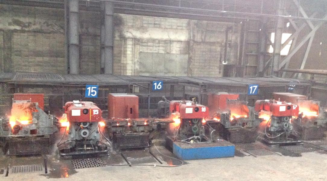
ในเดือนธันวาคม 2025 VR MASTER ได้รับความไว้วางใจจากลูกค้ากลุ่มอุตสาหกรรมเหล็กรายใหญ่ในอินโดนีเซีย ในการเข้าปรับปรุงคุณภาพไฟฟ้า (Power Quality) ให้กับโรงรีดเหล็กแผ่น (Plate Mill) แห่งใหม่ โดยมุ่งเน้นการแก้ปัญหาความผันผวนของระบบไฟฟ้าที่มีความซับซ้อนสูง เพื่อให้กระบวนการผลิตเป็นไปอย่างราบรื่นและมีประสิทธิภาพสูงสุด